Tube Preamp VST Plugin

DSP, Plugin and Host development discussion.
RELATED
PRODUCTS

Post

Hi there,

several weeks ago, I've posted some DIY projects in the corresponding topic, here at KVR audio.

Now, I want to present my latest work, which is part of my final thesis. I wrote this thesis in cooperation with db audiotechnik GmbH. The goal was to implement a tube preamp on a SHARC DSP. Furthermore, I've used the algorithm to build a VST plugin.

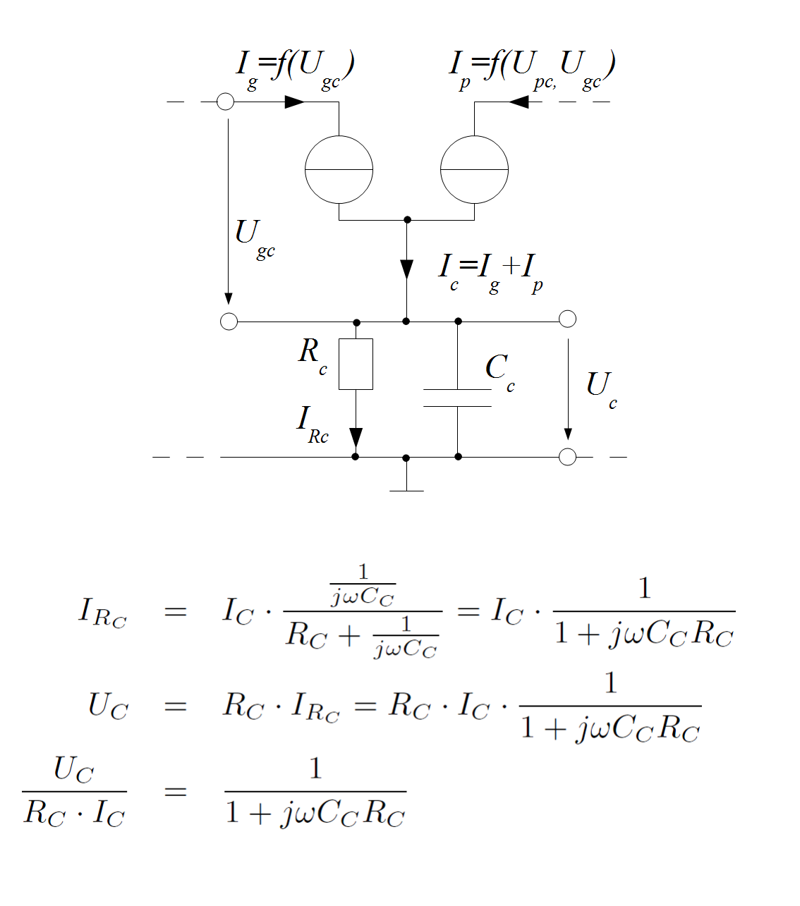
First I had to develope a digital tube model. This model was derived from the characteristic curves of data sheets of real tubes. Next, this model was used to implement a plate follower stage. Therefore, the state space representation of the electric circuit was digitised. Finally, I've created a simple GUI for the plugin, that displays the circuit. Detailed information can be found on my website: http://philaudio.wordpress.com/research/tube-preamp/

Image

The VST plugin can be downloaded from my blog (link above).

The plugin was built with the JUCE library.

Comments and suggestions are welcome!

Thanks,
Philipp!
Last edited by Oddgit on Sun Nov 04, 2012 6:14 pm, edited 2 times in total.
Audio Software And Hardware projects:
http://philaudio.wordpress.com

Post

Very nice sound and enjoyable time when moving the dials around.

Cheers Philipp :D

Post

On the google code page it claims GPL3 yet there's no source to be found. I'm confused.

Post

As far as I can tell, it shows the right kind of clipping on the curves. Do you have a paper in English instead of the thesis in German?
~stratum~

Post

Looks very interesting.
Any reasons for using a ECC82 instead of the (in gain stage more commonly used) ECC83?
stratum wrote:Do you have a paper in English instead of the thesis in German?
There is an english abstract (actually it's more detailed than your usual abstract) on the linked page.


Chris

Post

Just tried it on a kickdrum and it really fattened the sound up. A little confusing at first but great fun turning all the nobs around till the sound starts to gel. The sound then,deep and fat and definitely a good quality, i can see me using this for running weak sounds through to give them some extra gain and harmonics, thanks for the freebie.

Post

Hi everybody,

thanks a lot for all the feedback!
mystran wrote:On the google code page it claims GPL3 yet there's no source to be found. I'm confused.
Yes, I'm sorry about that. I will upload the code as soon as possible. I've used google code primarily to provide the download of the plugin.

stratum wrote:As far as I can tell, it shows the right kind of clipping on the curves. Do you have a paper in English instead of the thesis in German?
Unfortunately, the thesis was written in German only. At the moment I don't have the time to translate the whole thesis into English. The short summary on my blog is all I can offer at the moment.
mahaya wrote:Looks very interesting.
Any reasons for using a ECC82 instead of the (in gain stage more commonly used) ECC83?

[...]


Chris
I've modeled the circuit with an ECC83 (12AX7) as well. But in my opinion, the ECC82 (12AU7) sounded a litte bit better (more dynamic and less compression). A big advantage of the ECC83 is the high amplification factor. However the amplification factor is not important in the digital domain, so I decided to use the better sounding tube.

Best,
Philipp!
Audio Software And Hardware projects:
http://philaudio.wordpress.com

Post

Oddgit wrote:
mystran wrote:On the google code page it claims GPL3 yet there's no source to be found. I'm confused.
Yes, I'm sorry about that. I will upload the code as soon as possible. I've used google code primarily to provide the download of the plugin.


Philipp!
Hopefully the source code could explain a couple of things (for us non-german speakers). I'm especially intrigued by how the cathode voltage lag is actually implemented.

Cool project btw.

Andrew

Post

Causing massive crashes here in tracktion. Otherwise sounds good.

Post

Hi,
Ichad.c wrote:[...]

Hopefully the source code could explain a couple of things (for us non-german speakers). I'm especially intrigued by how the cathode voltage lag is actually implemented.

Cool project btw.

Andrew
the implementation of the cathode biasing is quite simple. The implemented plate follower looks like this:

Image

If the grid current and the plate current are assumed as ideal current sources, we get the following:

Image

The cathode current is the sum of grid current and plate current. The Grid current is a function of grid voltage, plate current is a function of grid voltage and plate voltage. With the complex current divider, we get the current through the cathode resistor. This finally leads to the cathode voltage by Ohm's law.

It can be seen, that this is a simple one pole lowpass RC-filter with input Ic*Rc and output Uc.
metamorphosis wrote:Causing massive crashes here in tracktion. Otherwise sounds good.
I've tested the plugin with Cubase LE4 and Windows 7 (32 bit). That works without problems... I'm sorry, I don't know where the problem lies.

Best,
Philipp.
Audio Software And Hardware projects:
http://philaudio.wordpress.com

Post

Oddgit wrote:
mystran wrote:On the google code page it claims GPL3 yet there's no source to be found. I'm confused.
Yes, I'm sorry about that. I will upload the code as soon as possible. I've used google code primarily to provide the download of the plugin.
No need to apologize, it's simply that I wished I'd been able to check some things without having to bother asking... anyway I'll ask instead:

1. How do you solve the circuit? Do you use something standard like Trapezoid+Newton or do you use some formulation (eg possibly ignoring some of the feedback effects) that allows an explicit solution?

2. Given that the grid controls the plate current, the plate voltage is dependent on the load impedance which in the circuit isn't strictly resistive; do you take this into account or do you just ignore the reactive load? Or do you calculate equivalent Ra from the current circuit state? Note that I'm not trying to imply it's significant in this particular circuit; I'm just wondering about the generality of your approach.

Post

Hi,

maybe things become more clear with this block diagram:

Image
mystran wrote: 1. How do you solve the circuit? Do you use something standard like Trapezoid+Newton or do you use some formulation (eg possibly ignoring some of the feedback effects) that allows an explicit solution?
First, the circuit is described in the frequency domain. To get the transfer functions from the circuit, the impedance of the capacitors is used (1/jwC). Since the obtained differential equations can hardly be solved explicit, they are solved recursively in the time domain:

Freq -> Time -> Discrete
jwX -> dX/dt -> (X[n]-X[n-1])*fs

This method causes a little error when calculating the cathode voltage. The cathode voltage is delayed one sample. But since it changes very slow compared to audio signals, this effect can be neglected.
mystran wrote: 2. Given that the grid controls the plate current, the plate voltage is dependent on the load impedance which in the circuit isn't strictly resistive; do you take this into account or do you just ignore the reactive load? Or do you calculate equivalent Ra from the current circuit state? Note that I'm not trying to imply it's significant in this particular circuit; I'm just wondering about the generality of your approach.
In my model, I assume the working resistor to be strictly resistive. The impedance of the load is not taken into account. The plate voltage is calculated by equalling the load line of the working resistor and the characteristic curves of the tube.
When two stages are connected in series, the output impedance of the first stage is used to calculate the input circuit of the second stage.

Hopefully it's more clear now.

Best,
Philipp.
Last edited by Oddgit on Thu Aug 02, 2012 9:41 am, edited 1 time in total.
Audio Software And Hardware projects:
http://philaudio.wordpress.com

Post

Oddgit wrote:
metamorphosis wrote:Causing massive crashes here in tracktion. Otherwise sounds good.
I've tested the plugin with Cubase LE4 and Windows 7 (32 bit). That works without problems... I'm sorry, I don't know where the problem lies.

Best,
Philipp.
It lies with the plugin.
I have about 300 different plugs, none of which I have issues with.
Good luck.

Post

Your latest work is excellent work :) This plug in sounds fabulous!!!

Thank you :)

Post

Oddgit wrote: First, the circuit is described in the frequency domain. To get the transfer functions from the circuit, the impedance of the capacitors is used (1/jwC). Since the obtained differential equations can hardly be solved explicit, they are solved recursively in the time domain:

Freq -> Time -> Discrete
jwX -> dX/dt -> (X[n]-X[n-1])*fs

This method causes a little error when calculating the cathode voltage. The cathode voltage is delayed one sample. But since it changes very slow compared to audio signals, this effect can be neglected.
By "explicit" I referred to "explicit integration method" meaning the derivative of a given sample can be calculated "explicitly" in contrast to "implicit" methods which need to solve the final result (usually using some iterative method) in order to calculate the derivative.

Anyway from the finite difference and the fact that you mention one sample delay, I'd infer that you're using implicit Euler with an additional feedback delay to make the solution explicit.

I know next to nothing about tubes, so I'm not criticizing just curious.
mystran wrote: 2. Given that the grid controls the plate current, the plate voltage is dependent on the load impedance which in the circuit isn't strictly resistive; do you take this into account or do you just ignore the reactive load? Or do you calculate equivalent Ra from the current circuit state? Note that I'm not trying to imply it's significant in this particular circuit; I'm just wondering about the generality of your approach.
In my model, I assume the working resistor to be strictly resistive. The impedance of the load is not taken into account. The plate voltage is calculated by equalling the load line of the working resistor and the characteristic curves of the tube.
When two stages are connected in series, the output impedance of the first stage is used to calculate the input circuit of the second stage.

Hopefully it's more clear now.
I see. So the expectation is that load impedance is high compared to the plate resistor?

Post Reply

Return to “DSP and Plugin Development”