
Well, the current generation of DSP chips have a lot of processing power and programming flexibility, I can't imagine anyone in the current age trading e.g. 10% filter length for 1 dB ripple.earlevel wrote:especially in a stomp box where you won't be chaining a bunch of identical units (though it doesn't happen often with plugins either), I wouldn't hesitate at using that tool

Trying to understand oversampling
-

- KVRAF
- 4021 posts since 7 Sep, 2002
-
- KVRian
- 653 posts since 4 Apr, 2010
Hi S0lo,S0lo wrote:Do you mean original nyquist or upsampled nyquist?matt42 wrote: Sorry, zero padding doesn't have notches or even a slope. Zero padding retains the original frequencies plus spectral mirroring above nyquist.
If original, then if the original signal wasn't bandlimited under it's nyquist (i.e aliasing), Will the zero padding images cross original nyquist into audible range? if so, then filtering wouldn't remove that part of aliasing, would it?
If you've read the classic DSP text books, you've probably seen that sampled audio has images that repeat well beyond the sample rate (theoretically, to infinity in both positive and negative directions—for practical reasons, we can ignore the negative because they can't exist without the positive in real systems). That's theoretical, of course, and due to theoretically perfect impulses, but if we get as close as we can in actual electronic circuitry, you would indeed get these repeating images—but they would drop off with frequency due to not having infinite harmonics in the real-world impulses. This is why we use a lowpass filter in the DAC output, to remove those images. (Yes, impulses are really inefficient in practice, and we really use something more like zero-order-hold steps, then compensate for the frequency response errors that causes—that doesn't change the fact that the ideal is that samples represent impulses.)
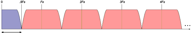
If you're comfortable with that, then zero-padding becomes obvious. It simply moves the goal posts while leaving the field intact. That is, If you draw out the passband and its aliases (if SR is 48 kHz, your audio site in 0-24k, a mirrored image from 24-48k, a repeat of your audio modulated up to 48k-72k, its mirror at 72k-96k...), it all stays in place when you stuff a zero in between each sample—the only thing that changes is SR is now 96 kHz. That's why we follow it with a windowed-sinc (or other) lowpass filter that rolls off before SR/4 (24k). After that you'll still have your audio at 0-24k, and its mirror at 72k-96k (because we wiped out the first mirror and first repeat with the lowpass).
Maybe pictures help; first the original:
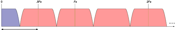
Now we insert a zero between each sample—note only Fs moves, doubling due to doubling of samples:
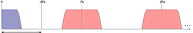
After lowpass filtering to clear the alias in the now-widened audio band:
The above is from my article here; other sample rate conversion articles that might be helpful here.
Last edited by earlevel on Sun Aug 28, 2016 9:05 pm, edited 2 times in total.
My audio DSP blog: earlevel.com
-
- KVRian
- 1273 posts since 9 Jan, 2006
Original nyquist, so the spectral mirroring doesn't overlap with the original frequency content.S0lo wrote:Do you mean original nyquist or upsampled nyquist?
If original, then if the original signal wasn't bandlimited under it's nyquist (i.e aliasing), Will the zero padding images cross original nyquist into audible range? if so, then filtering wouldn't remove that part of aliasing, would it?
As for "if the original signal wasnt band limited" well the original signal only contains frequencies upto original nyquist. If there's already aliasing or noise then it falls within the band limited spectrum.
-

- KVRian
- 1253 posts since 31 Dec, 2008
Thanks for the elaborate explanation, All is well and understood,earlevel wrote:Hi S0lo,S0lo wrote:Do you mean original nyquist or upsampled nyquist?matt42 wrote: Sorry, zero padding doesn't have notches or even a slope. Zero padding retains the original frequencies plus spectral mirroring above nyquist.
If original, then if the original signal wasn't bandlimited under it's nyquist (i.e aliasing), Will the zero padding images cross original nyquist into audible range? if so, then filtering wouldn't remove that part of aliasing, would it?
If you've read the classic DSP text books, you've probably seen that sampled audio has images that repeat well beyond the sample rate (theoretically, to infinity in both positive and negative directions—for practical reasons, we can ignore the negative because they can't exist without the positive in real systems). That's theoretical, of course, and due to theoretically perfect impulses, but if we get as close as we can in actual electronic circuitry, you would indeed get these repeating images—but they would drop off with frequency due to not having infinite harmonics in the real-world impulses. This is why we use a lowpass filter in the DAC output, to remove those images. (Yes, impulses are really inefficient in practice, and we really use something more like zero-order-hold steps, then compensate for the frequency response errors that causes—that doesn't change the fact that the ideal is that samples represent impulses.)
If you're comfortable with that, then zero-padding becomes obvious. It simply moves the goal posts while leaving the field intact. That is, If you draw out the passband and its aliases (if SR is 48 kHz, your audio site in 0-24k, a mirrored image from 24-48k, a repeat of your audio modulated up to 48k-72k, its mirror at 72k-96k...), it all stays in place when you stuff a zero in between each sample—the only thing that changes is SR is now 96 kHz. That's why we follow it with a windowed-sinc (or other) lowpass filter that rolls off before SR/4 (24k). After that you'll still have your audio at 0-24k, and its mirror at 72k-96k (because we wiped out the first mirror and first repeat with the lowpass).
Maybe pictures help; first the original:
Now we insert a zero between each sample—note only Fs moves, doubling with out doubling of samples:
After lowpass filtering to clear the alias in the now-widened audio band:
The above is from my article here; other sample rate conversion articles that might be helpful here.
Now my question is, what if the original (in your first figure) had frequencies crossing 0.5fs, hence mirrored bellow 0.5fs. Obviously, the whole point of doing oversampling (in anti-aliasing) is to remove that mirroring (by doubling the bandwidth). Now if zero padding introduces another image at the old fs, it seams it would cross 0.5fs and go down below it, BECAUSE the original did so going above it, so creating aliasing again!!. Isn't it?
www.solostuff.net
Advice is heavy. So don’t send it like a mountain.
Advice is heavy. So don’t send it like a mountain.
-
- KVRian
- 1273 posts since 9 Jan, 2006
The original signal can't contain frequencies above 0.5 Fs.
For example if we had a crappy non band limited saw wave it will contain aliases. These will be below nyquist as the signal can't represent higher frequencies - thats why they alias. If we upsample this noisey signal we will still have the same undesirable noise in the upsampled signal.
For example if we had a crappy non band limited saw wave it will contain aliases. These will be below nyquist as the signal can't represent higher frequencies - thats why they alias. If we upsample this noisey signal we will still have the same undesirable noise in the upsampled signal.
Last edited by matt42 on Sun Aug 28, 2016 8:24 pm, edited 1 time in total.
-
- KVRian
- 1253 posts since 31 Dec, 2008
Yea, what I meant is aliased, mirrored, NOT bandlimited.matt42 wrote:The original signal can't conatain frequencies above 0.5 Fs
www.solostuff.net
Advice is heavy. So don’t send it like a mountain.
Advice is heavy. So don’t send it like a mountain.
-
- KVRAF
- 2256 posts since 29 May, 2012
If it was aliased previously for some reason, there is no 'filter' in the usual sense that can fix that. One can remove already introduced aliasing only in special cases under which something definite is known about the signal, like saying if we are sure that a particular signal does not contain anything below 500Hz and if it turns out that ADC result contains those, they we know, these are aliases of frequencies above nyquist (and that the ADC is a crappy one). One can algorithmically fix this, even though it may not be easy.Yea, what I meant is aliased, mirrored, NOT bandlimited
~stratum~
-
- KVRian
- 1253 posts since 31 Dec, 2008
Let me put this in another way, If I had a naive sawtooth. Is there a way to reduce the aliasing in that using oversampling.matt42 wrote:The original signal can't contain frequencies above 0.5 Fs.
For example if we had a crappy non band limited saw wave it will contain aliases. These will be below nyquist as the signal can't represent higher frequencies - thats why they alias. If we upsample this noisey signal we will still have the same undesirable noise in the upsampled signal.
I have to admit I know the answer here, as I've already tried it in my synth, BUT not with zero stuffing. Just running the synth at a higher rate then filtering and decimating. And I know it's inefficient. I'm asking because I want to know if zero padding is useful in that matter or not. So yes, it would still help if I know that.
www.solostuff.net
Advice is heavy. So don’t send it like a mountain.
Advice is heavy. So don’t send it like a mountain.
-
- KVRAF
- 2256 posts since 29 May, 2012
You do not zero pad in that case, what needs to be done is to sample that saw at an higher sampling rate (thus reduce aliasing), not oversampling. In fact, one cannot oversample a saw in the proper sense of the term as it means using a sample rate higher than what is necessary. Since a saw contains frequencies up to infinity, and one cannot have a sampling rate higher than 2*infinity (which is still infinity and meaningless), then by definition, one cannot oversample a saw. One can sample it, however, and have some aliasing, and if you oversample it afterwards, that would just be a waste of cpu cycles.
In practice there are dedicated algorithms for this, and it is not necessary to sample a saw in the 'naive' way (have a look at the minBLEP thread somewhere below in the forum).
In practice there are dedicated algorithms for this, and it is not necessary to sample a saw in the 'naive' way (have a look at the minBLEP thread somewhere below in the forum).
~stratum~
-
- KVRian
- 1273 posts since 9 Jan, 2006
Actually the answer to this was in my reply. Once a signal is aliased it's aliased. Upsampling afterwards just upsamples aliased frequencies in the same way as any other frequency. There's no way to distinguish the aliased vs desired frequencies. So no, zero padding an aliased signal won't help reduce those aliases.S0lo wrote:Let me put this in another way, If I had a naive sawtooth. Is there a way to reduce the aliasing in that using oversampling.matt42 wrote:The original signal can't contain frequencies above 0.5 Fs.
For example if we had a crappy non band limited saw wave it will contain aliases. These will be below nyquist as the signal can't represent higher frequencies - thats why they alias. If we upsample this noisey signal we will still have the same undesirable noise in the upsampled signal.
I have to admit I know the answer here, as I've already tried it in my synth, BUT not with zero stuffing. Just running the synth at a higher rate then filtering and decimating. And I know it's inefficient. I'm asking because I want to know if zero padding is useful in that matter or not. So yes, it would still help if I know that.
-
- KVRian
- 1253 posts since 31 Dec, 2008
I take it then that all these synths that use oversampling to reduce aliasing, have to actually run the synth internally at the higher oversampling rate. Only then filter, then decimate ? Well thats what I'm doing any way, and it's working good, but CPU is high as I increase the oversampling factor. Trying to find ways to reduce the CPU.matt42 wrote:Actually the answer to this was in my reply. Once a signal is aliased it's aliased. Upsampling afterwards just upsamples aliased frequencies in the same way as any other frequency. There's no way to distinguish the aliased vs desired frequencies. So no, zero padding an aliased signal won't help reduce those aliases.S0lo wrote:Let me put this in another way, If I had a naive sawtooth. Is there a way to reduce the aliasing in that using oversampling.matt42 wrote:The original signal can't contain frequencies above 0.5 Fs.
For example if we had a crappy non band limited saw wave it will contain aliases. These will be below nyquist as the signal can't represent higher frequencies - thats why they alias. If we upsample this noisey signal we will still have the same undesirable noise in the upsampled signal.
I have to admit I know the answer here, as I've already tried it in my synth, BUT not with zero stuffing. Just running the synth at a higher rate then filtering and decimating. And I know it's inefficient. I'm asking because I want to know if zero padding is useful in that matter or not. So yes, it would still help if I know that.
www.solostuff.net
Advice is heavy. So don’t send it like a mountain.
Advice is heavy. So don’t send it like a mountain.
-
- KVRist
- Topic Starter
- 65 posts since 1 Apr, 2016
Thanks guys! a lot of info in this thread!
I've playing with different filters, but I need filter with kernels of 97 or more to get rid some aliasing.
I will investigate more about those you have recommended. I will read about polyphase filters too.
I've playing with different filters, but I need filter with kernels of 97 or more to get rid some aliasing.
I will investigate more about those you have recommended. I will read about polyphase filters too.
-

- KVRAF
- 7890 posts since 12 Feb, 2006 from Helsinki, Finland
Yes, the very essence of oversampling: run stuff that aliases at higher sampling rate, so you get a chance to filter some of it out.. and yes, if you oversample by a factor of N then you need to process N times as many samples and any per-sample processing you do will take about N times more CPU.S0lo wrote: I take it then that all these synths that use oversampling to reduce aliasing, have to actually run the synth internally at the higher oversampling rate. Only then filter, then decimate ? Well thats what I'm doing any way, and it's working good, but CPU is high as I increase the oversampling factor. Trying to find ways to reduce the CPU.
Note that most synths don't really use oversampling as the only means of reducing aliasing. Things like saw-waves would require stupid amounts of oversampling (eg. x1024 or so would be a good starting point) to get "clean" results, so most synths would use mipmapped wavetables or BLEPs or something like that to generate band-limited waveforms and then rely on oversampling to handle additional aliasing created later (eg. distortion, non-linear filters).
-
- KVRAF
- 2256 posts since 29 May, 2012
There is a simple noise reduction algorithm that involves setting too small FFT bins to zero (plus some overlapped windows so that it would work in the end as expected) to reduce hiss noise. I guess it could also be used to clean up any remaining aliasing after all other reasonable methods are applied (higher rate sampling, binBLEP, etc.) I don't know if it would be worth the extra cpu cycles spent and wouldn't work in cases aliased parts of the signal strongly correlate with the actual parts (so that they fell into very close fft bins that would already contain smearing of actual signal)
~stratum~
-
- KVRAF
- 7400 posts since 17 Feb, 2005
So we can't filter it out?stratum wrote:There is a simple noise reduction algorithm that involves setting too small FFT bins to zero (plus some overlapped windows so that it would work in the end as expected) to reduce hiss noise. I guess it could also be used to clean up any remaining aliasing after all other reasonable methods are applied (higher rate sampling, binBLEP, etc.) I don't know if it would be worth the extra cpu cycles spent and wouldn't work in cases aliased parts of the signal strongly correlate with the actual parts (so that they fell into very close fft bins that would already contain smearing of actual signal)


