Splitting Bands with Linkwitz-Riley

DSP, Plugin and Host development discussion.
RELATED
PRODUCTS

Post

AUTO-ADMIN: Non-MP3, WAV, OGG, SoundCloud, YouTube, Vimeo, Twitter and Facebook links in this post have been protected automatically. Once the member reaches 5 posts the links will function as normal.
I am trying to build a multi-band[4] compressor. Therefore I need to split the signal into 4 bands. I naturally stumbled upon https://en.wikipedia.org/wiki/Linkwitz% ... ley_filter (https://en.wikipedia.org/wiki/Linkwitz%E2%80%93Riley_filter)
This means that summing the low-pass and high-pass outputs, the gain at the crossover frequency will be 0 dB, so the crossover behaves like an all-pass filter, having a flat amplitude response with a smoothly changing phase response.
I found an appropriate implementation http://www.musicdsp.org/showArchiveComm ... hiveID=266 (http://www.musicdsp.org/showArchiveComment.php?ArchiveID=266) which I ported to Java for testing.

Setup:
Now I wrote some code to create a 10sec chirp from 20Hz - 18kHz. I separated the signal at 2000Hz by the first Linkwitz-Riley to get two bands [low, high]. Both bands will then be split by two other Linkwitz-Riley to divide them again at 500Hz and 8kHz. So in theory I should have created four bands from 0-500Hz, 500Hz-2kHz, 2kHz-8kHz & lastly 8kHz-Nyquist. To test if everything works I put all bands into one wav-file to be opened in a sample-editor including the sum of the first split and the sum of the 4 bands. Please check the attached screenshot.

Now my problem:
It looks like the sum of the first split does follow the properties as described on wikipedia (flat response, no energy lost). However after the second split, energy loss is introduced at the first split-frequency. While it looks like magic to me, there must be a reasonable explanation for this behaviour. Either the loss was already there but barely visible and got increased after the second split or I did not quite understand the concept of cross-filters, group delay and phase shifting. Any help is appreciated.

Following the setup code and I attached the screenshot of the wav-file.

Code: Select all (#)

public final class BandSplitMain {
	private static final int SAMPLE_RATE = 48000;
	private static final String TMP_FOLDER = "tmp/";

	public static void main( @Nonnull final String[] args ) throws IOException {
		final int length = SAMPLE_RATE * 10; // 10 seconds
		final double[] source = new double[length];
		final double[] c0 = new double[length];
		final double[] c1 = new double[length];
		final double[] b0 = new double[length];
		final double[] b1 = new double[length];
		final double[] b2 = new double[length];
		final double[] b3 = new double[length];
		final double[] b_mix = new double[length];
		final double[] c_mix = new double[length];
		final double incMin = 20.0 / SAMPLE_RATE;
		final double incMax = 18000.0 / SAMPLE_RATE;
		final double incMult = Math.pow( incMax / incMin, 1.0 / ( double ) length );
		double phase = 0.0;
		double phaseIncr = incMin;
		for( int i = 0; i < length; ++i ) {
			source[i] = Math.sin( phase * 2.0 * Math.PI );
			phaseIncr *= incMult;
			phase += phaseIncr;
		}

		final LinkwitzRiley crossM = new LinkwitzRiley(); // split source into 2 bands
		crossM.setFreq( 2000.0, SAMPLE_RATE );
		crossM.process( source, c0, c1, length );

		final LinkwitzRiley crossL = new LinkwitzRiley(); // split lower band into 2 sub-bands
		crossL.setFreq( 500.0, SAMPLE_RATE );
		crossL.process( c0, b0, b1, length );

		final LinkwitzRiley crossH = new LinkwitzRiley(); // split higher band into 2 sub-bands
		crossH.setFreq( 8000.0, SAMPLE_RATE );
		crossH.process( c1, b2, b3, length );

		for( int i = 0; i < length; ++i ) {
			c_mix[i] = c0[i] + c1[i]; // sum first split to check the outcome
		}
		for( int i = 0; i < length; ++i ) {
			b_mix[i] = b0[i] + b1[i] + b2[i] + b3[i]; // sum second splits to check the outcome
		}
		final byte[] wavFile = WavEncoder.encode32( new double[][]{ source, c0, c1, c_mix, b0, b1, b2, b3, b_mix }, SAMPLE_RATE );
		final FileOutputStream fos = new FileOutputStream( TMP_FOLDER + "noise.wav" );
		fos.write( wavFile );
		fos.close();
	}
}
Attached screenshot shows the different signals:
1. Chirp 20Hz-18kHz
2. First split low (<8kHz)
3. First split high (>8kHz)
4. Sum of 2, 3 looks perfectly flat
5. Second split low, low (<500Hz)
6. Second split low, high (500Hz-2kHz)
7. Second split high, low (2kHz-8kHz)
8. Second split high, high (>8kHz)
9. Sum of 5, 6, 7, 8 does not look flat at all around 8kHz (frequency of first split)
You do not have the required permissions to view the files attached to this post.

Post

After more research I should add an Allpass filter to the high-component of each stage of splitting. I presume the same cutoff frequency but have no idea for the Q value.

Post

Linkwitz-Riley is also described as butterworth squared - in other words two butterworth chained one after the other. The phase shift of two lowpass filters is the same as a single allpass filter stage, assuming each low pass stage and the allpass have the same q. Here's a link to a thread with more info: viewtopic.php?f=33&t=479651&start=15 it includes diagrams this kind of structure

Post

Just to add why the allpass is needed. Say we spilt a signal into two with linkwitz-riley the combination of the two signals (low pass + high-pass) = allpass. This is fine for two a band system.

How about 3 bands. Well, we start by splitting the signal into two bands, just as before. But next we split the upper band again to get mid and high bands. The problem is the mid and high band combined is now an allpass filtered version of the original upper band. If we combine them with the low band there will be phase issues, so the low band needs filtering with the same allpass response as the upper band.

Post

Image

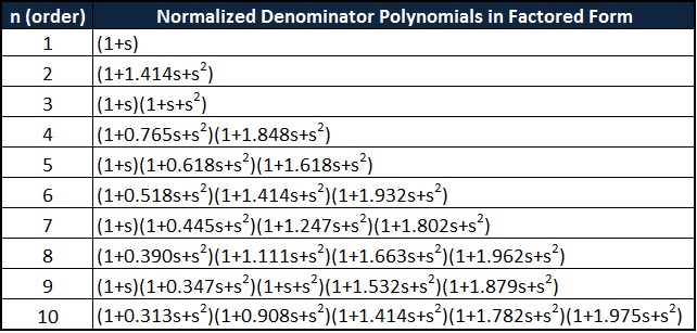
You can get 1/q values from this table. (1+s) is just a one pole low pass (1+x*s+s^2) is a two pole stage where x = 1/q. So, you can build butterworth filters up to 10th order, by chaining 1st and second order sections with q's derived from the table. For linkwitz riley just do two sets of each section. For the allpass, again just use the q values from the table, but this time no need to double up, as you want the butterworth response.

Edit: The short answer. For the musicdsp 4th order LR filter sqrt(2) is more accurate than the table value of 1.414.
Last edited by matt42 on Sat Feb 17, 2018 10:02 am, edited 1 time in total.

Post

Code you use for LP does not give good frequency response ... does it become flat when sample rate is, lets say, 4 times higher ... or does it have any effect in this issue?

<removed the response comparison>
Last edited by juha_p on Sat Feb 17, 2018 2:18 pm, edited 1 time in total.

Post

Hi Juha_p,

Comparing the low pass response isn't really the most important thing for LR filters. You need to compare what happens when recombining the separated bands. BLT will result in a perfectly flat allpass response. I'm not sure how close MZT could get.

Post

matt42 wrote:Hi Juha_p,

Comparing the low pass response isn't really the most important thing for LR filters. You need to compare what happens when recombining the separated bands. BLT will result in a perfectly flat allpass response. I'm not sure how close MZT could get.
OK, removed the comparison?

Post

matt42 wrote:BLT will result in a perfectly flat allpass response. I'm not sure how close MZT could get.
"Continuous magnitude matching" filters (not necessarily an MZT) can do the same (it's just important to keep in mind that the HP part won't have G@FN = 1, just like analog filters haven't). But this all is absolutely irrelevant to the op problem (the correction-phaseshifting is required regardless of the LP response (after all it may be not even LP at all if desired), the only important thing is A + B + C + ... = Allpass and everything else is deduced from this).
Last edited by Max M. on Sun Feb 18, 2018 2:47 am, edited 1 time in total.

Post

If op would like to test if there are any difference between LP with better frequency response and those used there, here are coefficients for 2nd order LP (for HP, use those you used in your plots) :

Code: Select all

#5. Second split low, low (<500Hz)
#6. Second split low, high (500Hz-2kHz)
#7. Second split high, low (2kHz-8kHz)
#8. Second split high, high (>8kHz)
#==========
#fs = 48kHz

#LP
fc = 500Hz [3.1362e-03   9.7767e-04  -2.3904e-05 1.00000  -1.90750   0.91159]
fc = 2kHz [4.3674e-02   1.3615e-02  -3.3288e-04 1.00000  -1.63361   0.69057]
fc = 8kHz [0.4017549   0.1246965  -0.0030519 1.00000  -0.70402   0.22742]

These are calculated using MZTi method.
Last edited by juha_p on Sun Feb 18, 2018 8:26 am, edited 3 times in total.

Post

juha_p wrote:If op would like to test if there are any difference between LP with better frequency response and those used there
(With all respect) These coefficients are pretty much useless for him since these LP/HP do not even form a Linkwitz-Riley pairs. (He might consider some non-BLT behavior after he solves his current problem but so far I'm afraid this info may only confuse him).
Last edited by Max M. on Sat Feb 17, 2018 7:24 pm, edited 1 time in total.

Post

accidental-doublepost

Post

While we're on the subject, could I ask a slightly OT question? It seems whenever one needs a crossover, L-R filters seem to be the answer. Why not odd-order Butterworth? They should have flatter passband than L-R of comparable order (if such thing did exist ;) ) Do I miss anything obvious?

Post


Post

Hmmm, pretty long text. Quite a few points I have not been aware of (so thanks for the link), however they seem to be relevant for the speaker design. It's not immediately obvious to me which of those stay important if we just use a crossover to split a signal path and then merge it back. Given that Butterworth order is odd, there is no +3dB bump in the sum, so what else could we care about? Maybe the in-phase property, but why?

Post Reply

Return to “DSP and Plugin Development”