

justin3am's Buchla clone builds
-

- KVRAF
- 2275 posts since 10 Jul, 2008 from Orbit NE US
Nice work.
gadgets an gizmos..make noise https://soundcloud.com/crystalawareness Restocked: 3/24
old stuff http://ww.dancingbearaudioresearch.com/
if this post is edited -it was for punctuation, grammar, or to make it coherent (or make me seem coherent).
old stuff http://ww.dancingbearaudioresearch.com/
if this post is edited -it was for punctuation, grammar, or to make it coherent (or make me seem coherent).
-

- KVRAF
- Topic Starter
- 12356 posts since 7 May, 2006 from Southern California
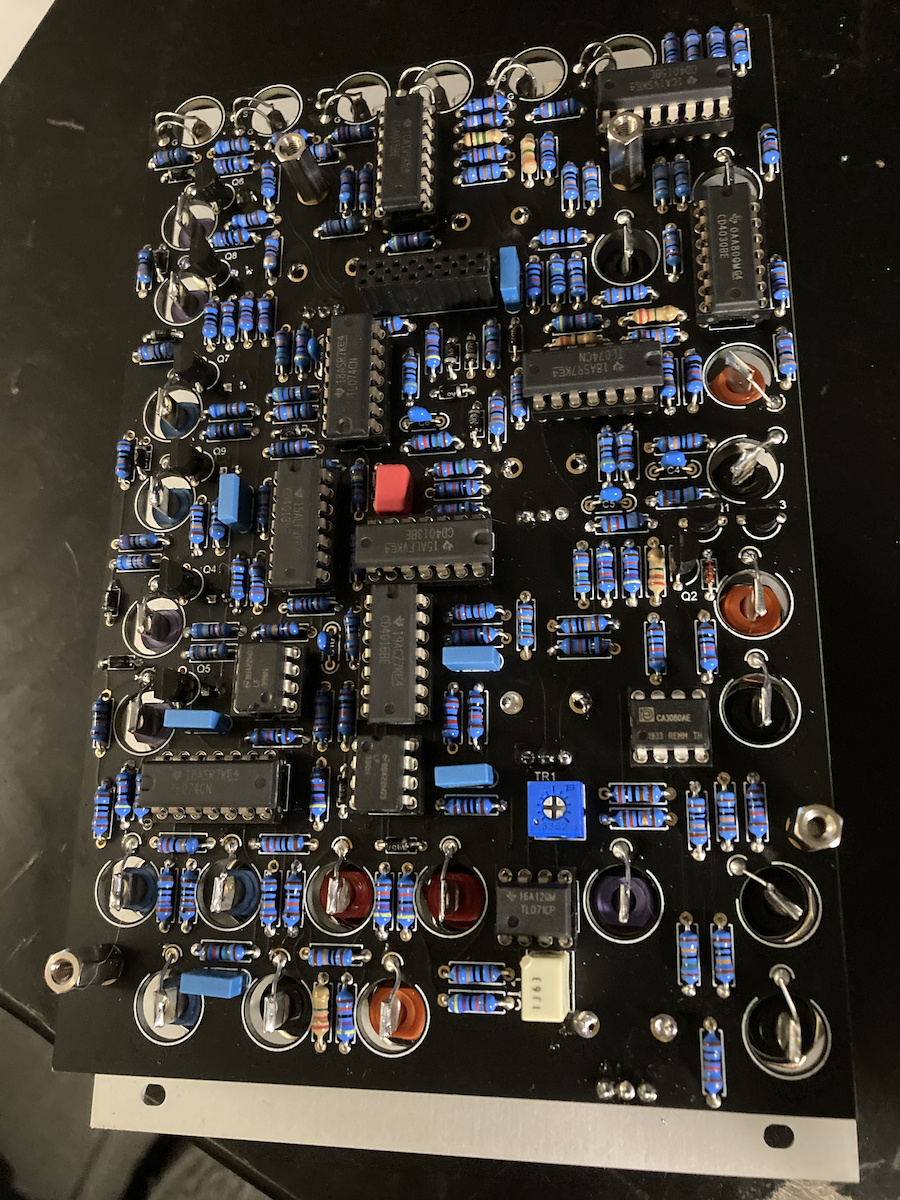
PCB 1 finished and mounted to the front panel.
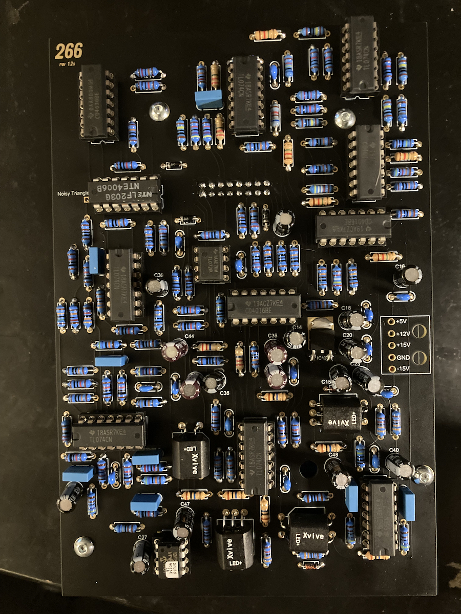
PCB 2 finished and mounted to PCB 1.
Top view.
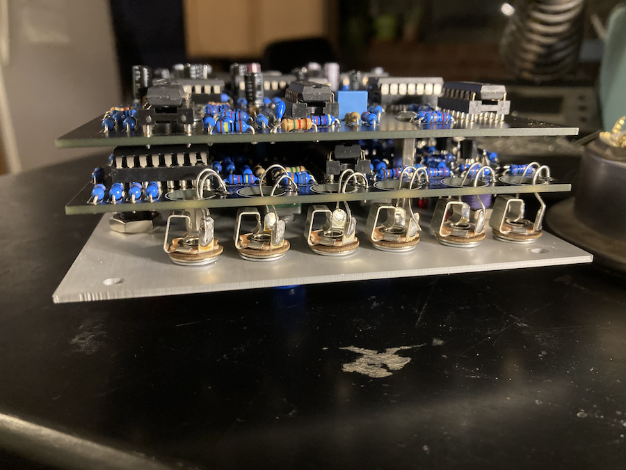
Bottom view.
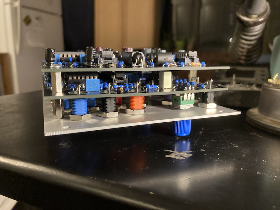
A shot with Orion in focus for some reason...
And finally the front.

PCB 2 finished and mounted to PCB 1.
Top view.
Bottom view.
A shot with Orion in focus for some reason...
And finally the front.
-
- addled muppet weed
- 105882 posts since 26 Jan, 2003 from through the looking glass
-
- KVRAF
- Topic Starter
- 12356 posts since 7 May, 2006 from Southern California
I still don't have my case yet. It's going to be another week or two. I thought about wiring them up with a bench supply or the PSU for my Frac stuff but I'm just going to wait.
I'll be working on the o&c next week. Since it's all tiny parts, I'm going to build it at my office where we have a nice microscope and a hot air station.
I'll be working on the o&c next week.
-
- KVRAF
- Topic Starter
- 12356 posts since 7 May, 2006 from Southern California
There are a few ways that Buchla modules aren't directly compatible with other modular standards.
For one, banana jacks are used for CV and pulse signals. Audio signal connections are made with Tinijax plugs, which are slightly larger than the more common 3.5mm mini jack. Instead of 1v/Oct scaling, oscillators are tuned to 1.2v/Oct. Also Pulse inputs expect specific voltage levels, so a standard gate signal won't trigger the Buchla envelopes or sequencers, in most cases.
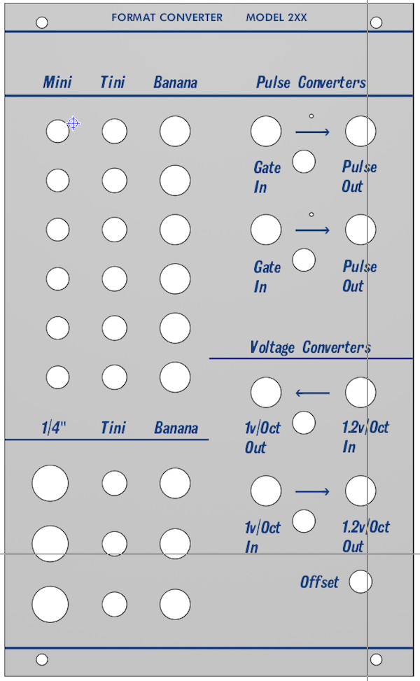
For all of these reasons, I needed to create a module that will allow me to interface my Buchla clone system with other modular systems. Portabellabz make some pulse and voltage converter circuit boards but they don't offer an assembled module, because the converters are usually built into a case, with the sockets coming out the back or the side of the case. Rather than doing that, I opted to design my own buchla format front panel. I made a vector graphic of the text and graphics in Inkscape, which I then imported on the FPD application from Front Panel Express. Using that application I was able to specify the dimensions of the front panel, and locations of drill holes.
Here is a screenshot of the design:
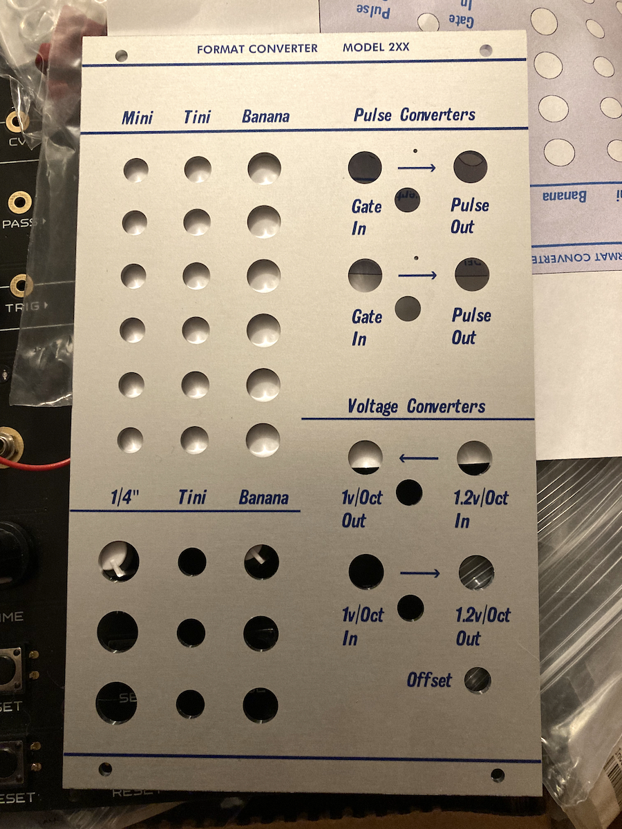
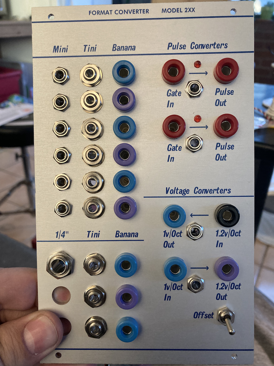
Here is the panel.
On the left side, is what we call a format jumbler. Just a passive mult/jack converter. These are useful for sending modulation and audio signals to and from eurorack modulars and other equipment, without any changes to the signals.
On the right side are the pulse and voltage converters. The pulse converters have LEDs to show the output signal. The 1v/Oct>1.2v/Oct converter has an offset switch for accommodating Buchla modules which don't like negative voltages.
I installed the jacks for the passive parts first.
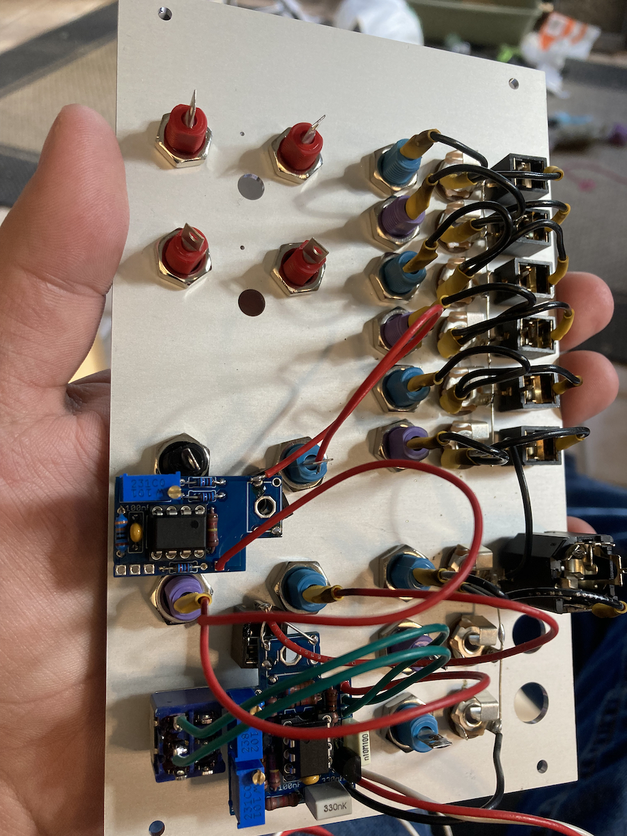
Then I wired up the pulse and voltage converters.
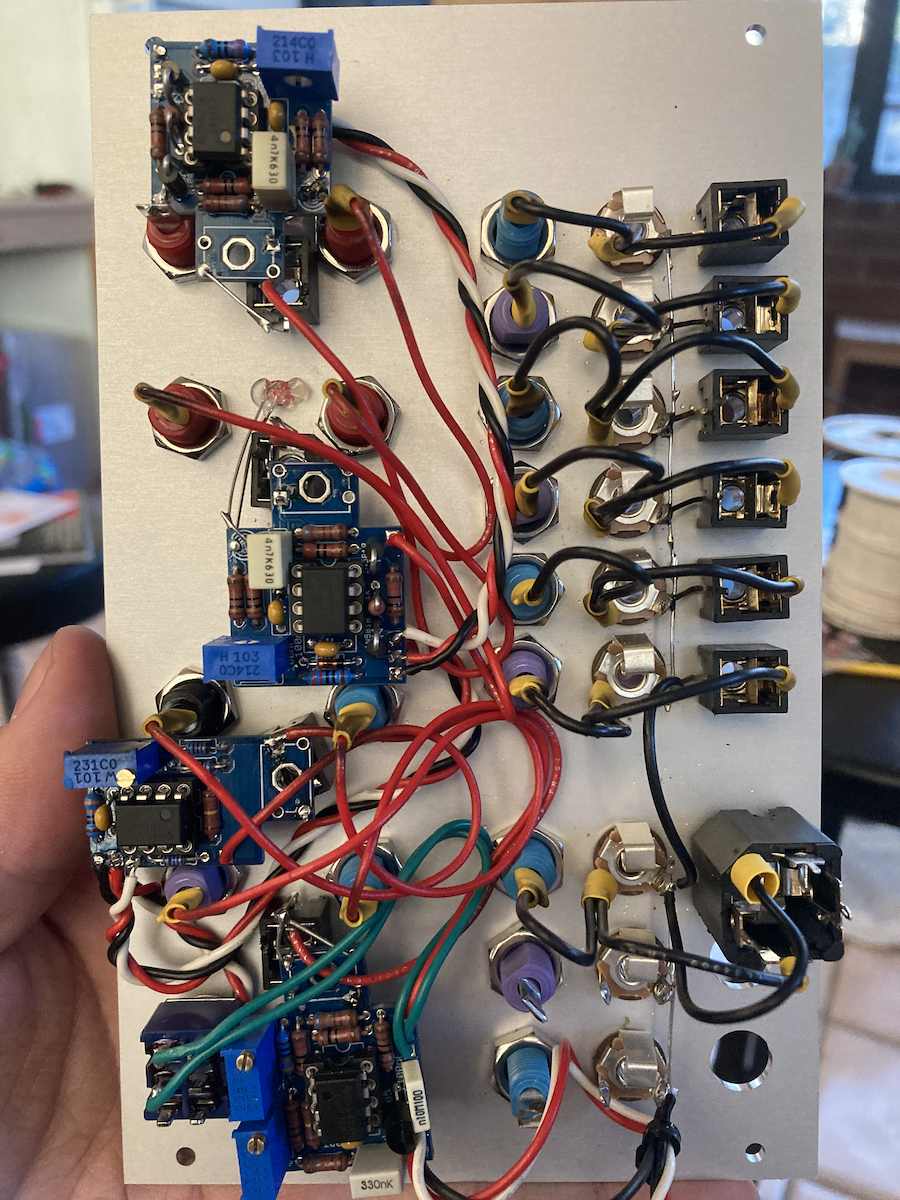
All done. Well I still need two more 1/4" jacks but, it's done enough to test it out and calibrate the converters.
For one, banana jacks are used for CV and pulse signals. Audio signal connections are made with Tinijax plugs, which are slightly larger than the more common 3.5mm mini jack. Instead of 1v/Oct scaling, oscillators are tuned to 1.2v/Oct. Also Pulse inputs expect specific voltage levels, so a standard gate signal won't trigger the Buchla envelopes or sequencers, in most cases.
For all of these reasons, I needed to create a module that will allow me to interface my Buchla clone system with other modular systems. Portabellabz make some pulse and voltage converter circuit boards but they don't offer an assembled module, because the converters are usually built into a case, with the sockets coming out the back or the side of the case. Rather than doing that, I opted to design my own buchla format front panel. I made a vector graphic of the text and graphics in Inkscape, which I then imported on the FPD application from Front Panel Express. Using that application I was able to specify the dimensions of the front panel, and locations of drill holes.
Here is a screenshot of the design:
Here is the panel.
On the left side, is what we call a format jumbler. Just a passive mult/jack converter. These are useful for sending modulation and audio signals to and from eurorack modulars and other equipment, without any changes to the signals.
On the right side are the pulse and voltage converters. The pulse converters have LEDs to show the output signal. The 1v/Oct>1.2v/Oct converter has an offset switch for accommodating Buchla modules which don't like negative voltages.
I installed the jacks for the passive parts first.
Then I wired up the pulse and voltage converters.
All done. Well I still need two more 1/4" jacks but, it's done enough to test it out and calibrate the converters.
-
- KVRAF
- Topic Starter
- 12356 posts since 7 May, 2006 from Southern California
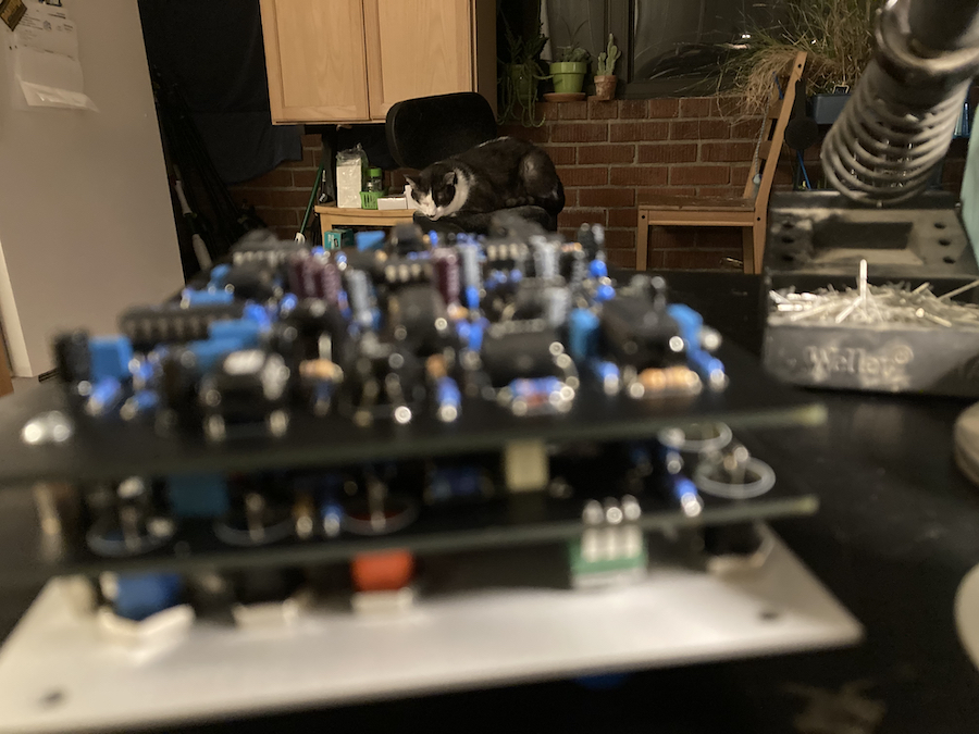
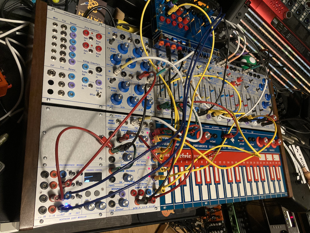
I did also build an Ornament & Crime module in the half panel size but I had to do that at work because my temporary work bench just isn't stable enough to do the SMT work. Unfortunately, I didn't have time to take pictures of that build as I went but here is a shot of the complete synth, including the O_c module:
-
- KVRAF
- 11054 posts since 19 Jun, 2008 from Seattle
Nice walk-through, and master workmanship!
I'm not a musician, but I've designed sounds that others use to make music. http://soundcloud.com/obsidiananvil
-
- KVRAF
- Topic Starter
- 12356 posts since 7 May, 2006 from Southern California
Thanks! That system is such a joy to use.
When I was building that stuff, I was thinking that I would likely build a larger clone system but I don't feel much need to do that at the moment. I'm still learning new things about these modules.
When I was building that stuff, I was thinking that I would likely build a larger clone system but I don't feel much need to do that at the moment. I'm still learning new things about these modules.
-
- KVRAF
- Topic Starter
- 12356 posts since 7 May, 2006 from Southern California
Hey thanks!

