



Logic in Bazille: Can It Be Done?
-

- KVRian
- 929 posts since 8 Mar, 2008 from Crestview, Florida
While there are no binary logic gates in Bazille, I can't help but wonder...what if we could make one within the Multiplexer using the various processors? I'm no expert in logic gates. I just want to create "polypulses" similar to those generated by the And/Or/Xor waveform mixing modes in Phonec 2; they have a wonderful, evolving dynamic I really enjoy. Any ideas
-

- KVRAF
- 5223 posts since 20 Jul, 2010
I mentioned this already to you but for the benefit of the studio audience (ha, that was almost a pun, well, it was a pun, but it was almost funny) if you run the distortion effect in hard clip mode, then feed it two sine waves, you'll get a similar effect to some logic effects, because due to the varying levels of the sine waves and how they interfere, you'll either get a high or a low output. Just set the input level to maximum and bring down the output level, then back off the resultant high-end frizz with the in-effect EQ.
Just don't play chords or you'll bring about the apocalypse
I'm working on a solution involving amplitude modulation, will report back. I'm sure that will get you close.
Just don't play chords or you'll bring about the apocalypse
I'm working on a solution involving amplitude modulation, will report back. I'm sure that will get you close.
http://sendy.bandcamp.com/releases < My new album at Bandcamp! Now pay what you like!
-

- KVRAF
- 13135 posts since 7 May, 2006 from Southern California
A VCA can be used to mimic AND logic. So you can use a Multiplexer to do that. It will only really work with square waves and pulses though. Maybe you can get some other types of logic by combining that signal or subtracting it from the original.
You can kinda use the Quanitizer as a comparator. Set the quantizer to 1 and route 5v and the signal you want to compare to a multiplexer, then the output of the multiplexer to the quantizer. The gain for the input to which 5v is connected becomes the threshold for the comparator. I've been trying to work out a way to simulate analog OR logic but you can kinda get digital OR logic using the Sample and Hold and a high pass filter (as an integrator). Edit: No you can't, I once tried to use the Sample and Hold as a Flip Flop but it only worked if the signals were in sync. I tried using the Quantizer as OR logic, using a similar patch to the Comparator one, but using two oscillators, instead of the 5v.
You can kinda use the Quanitizer as a comparator. Set the quantizer to 1 and route 5v and the signal you want to compare to a multiplexer, then the output of the multiplexer to the quantizer. The gain for the input to which 5v is connected becomes the threshold for the comparator. I've been trying to work out a way to simulate analog OR logic but you can kinda get digital OR logic using the Sample and Hold and a high pass filter (as an integrator). Edit: No you can't, I once tried to use the Sample and Hold as a Flip Flop but it only worked if the signals were in sync. I tried using the Quantizer as OR logic, using a similar patch to the Comparator one, but using two oscillators, instead of the 5v.
Last edited by justin3am on Sat Dec 31, 2016 10:32 pm, edited 2 times in total.
-
- KVRAF
- 13135 posts since 7 May, 2006 from Southern California
It would be useful to think about logic in terms of truth tables and then think about which states you require for the signal you are trying to generate. Often I find that I can get similar results by approaching the problem differently. So maybe a solution will only work as desired within a certain range but for the purpose of sound the method doesn't matter as much as the result.
Some neat things can be done by rectifying a symmetrical waveform and then subtracting the rectified signal from the original. Once you start changing the wave shape (so it's not symmetrical) the effect breaks but you can end up with some interesting sounds that way.
Some neat things can be done by rectifying a symmetrical waveform and then subtracting the rectified signal from the original. Once you start changing the wave shape (so it's not symmetrical) the effect breaks but you can end up with some interesting sounds that way.
-
- KVRian
- Topic Starter
- 929 posts since 8 Mar, 2008 from Crestview, Florida
By "subtract" do you mean mix a signal with an inverted version of that signal? Not sure what you mean.justin3am wrote:It would be useful to think about logic in terms of truth tables and then think about which states you require for the signal you are trying to generate. Often I find that I can get similar results by approaching the problem differently. So maybe a solution will only work as desired within a certain range but for the purpose of sound the method doesn't matter as much as the result.
Some neat things can be done by rectifying a symmetrical waveform and then subtracting the rectified signal from the original. Once you start changing the wave shape (so it's not symmetrical) the effect breaks but you can end up with some interesting sounds that way.
-
- KVRAF
- 13135 posts since 7 May, 2006 from Southern California
-

- u-he
- 30222 posts since 8 Aug, 2002 from Berlin
Unfortunately Bazille's original design phase predates Make Noise Maths by a few years. I didn't understand the possibilities of these functions before.
(might figure soemthing out at some point)
(might figure soemthing out at some point)
-
- KVRAF
- 13135 posts since 7 May, 2006 from Southern California
When did you start working on Bazille?
I see some mention of it as far back as 2004 (before I even knew what a Zebra was!)... was the concept the same at that time?
Bazille Alpha was released July 2009, I got my first Maths in November 2009. But still Maths wasn't the first to use logic in a modular context, Maths is largely inspired by Serge DUSG and Buchla 281, both of which date back to the '70s. Of course, Maths was my first experience with analog logic in synths, or at least that was the first time I understood how it worked. I think I used a Dopefer A172 before that but I didn't really that the effect was based on analog logic.
I'd be interested to hear more about the history of your products and their inspiration.
I see some mention of it as far back as 2004 (before I even knew what a Zebra was!)... was the concept the same at that time?
Bazille Alpha was released July 2009, I got my first Maths in November 2009. But still Maths wasn't the first to use logic in a modular context, Maths is largely inspired by Serge DUSG and Buchla 281, both of which date back to the '70s. Of course, Maths was my first experience with analog logic in synths, or at least that was the first time I understood how it worked. I think I used a Dopefer A172 before that but I didn't really that the effect was based on analog logic.
I'd be interested to hear more about the history of your products and their inspiration.
-
- KVRian
- Topic Starter
- 929 posts since 8 Mar, 2008 from Crestview, Florida
Well, that was a fun experiment! You made me get out a pencil and paper to make sense of it all. I thought it would be cool to restore the negative cycle and then shift the phase of it, so I mixed a half-wave rectified saw with a second phase-shifted saw, mixed with an inverted rectified version of itself. This completely restores the bottom half, but allows you to "break" the saw wave in a really fun way!yellowmix wrote:I did this with a sawtooth to nullify the second half, then used AND logic to add the second half using an inverter to achieve the Sylenth1 "tri-saw" (patch included): https://www.reddit.com/r/edmproduction/ ... ic_shapes/justin3am wrote:Some neat things can be done by rectifying a symmetrical waveform and then subtracting the rectified signal from the original. Once you start changing the wave shape (so it's not symmetrical) the effect breaks but you can end up with some interesting sounds that way.
Howard Scarr's TIPS & TRICKS folder contains examples he describes in the manual, including cancelling via rectifying (Multiplex tricks - half-wave rectify). It's essential reading.

(Now watch, someone will show a much easier way to do this and demonstrate how I am working WAY too hard again)

-
- KVRAF
- 13135 posts since 7 May, 2006 from Southern California
For combining waveforms, it's a lot of fun to use the Multiplexers as cross-faders at audio rate. Try this patch...
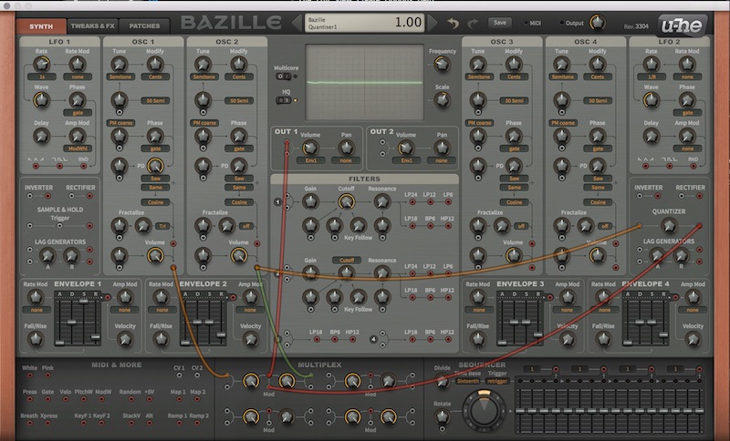
Move the phase control for osc1.
You can make the cross fader act more like a VC switch by feeding it a square wave. Set one oscillator to Tap Map and draw a square wave on one of the Mapping Generators. That will give you a better square than using the Square wave shape for the Oscillator.
Move the phase control for osc1.
You can make the cross fader act more like a VC switch by feeding it a square wave. Set one oscillator to Tap Map and draw a square wave on one of the Mapping Generators. That will give you a better square than using the Square wave shape for the Oscillator.
-
- KVRAF
- 13135 posts since 7 May, 2006 from Southern California
Oh yeah, I forgot to mention... if you want to visualize signals with a DC component (such as square waves or sample and hold output), there is a problem. There is an AC coupling filter before the oscilloscope! The best way I've found to see the effect of a DC signal is to route it to the Rotate CV input. Since the Rotate input moves the Snapshot Morph indicator, you can kinda see the wave shape.
It doesn't work for audio signals but you can change the oscillator range to check the shape and then change it back.
It doesn't work for audio signals but you can change the oscillator range to check the shape and then change it back.
-
- KVRist
- 89 posts since 7 Jan, 2011 from stockholm, sweden
Nice, I wish I thought of thatjustin3am wrote:The best way I've found to see the effect of a DC signal is to route it to the Rotate CV input. Since the Rotate input moves the Snapshot Morph indicator, you can kinda see the wave shape.
It doesn't work for audio signals but you can change the oscillator range to check the shape and then change it back.
. It'd be great if the scope could draw DC. Or better yet, there was an (additional?) scope that was not connected to the output.PhasePhckr (modular MPE VSTi) G+
Fatar88Lux (dyi MIDI brain) bitbucket
Assault Opera - sound cloud | spotify
Fatar88Lux (dyi MIDI brain) bitbucket
Assault Opera - sound cloud | spotify
-
- KVRAF
- 5223 posts since 20 Jul, 2010
What if the scope had a DC blocking on/off switch AND you could patch it from any source with cables? I think this might up the "edutainment" angle of Bazille considerably.ulph wrote:Nice, I wish I thought of thatjustin3am wrote:The best way I've found to see the effect of a DC signal is to route it to the Rotate CV input. Since the Rotate input moves the Snapshot Morph indicator, you can kinda see the wave shape.
It doesn't work for audio signals but you can change the oscillator range to check the shape and then change it back.
http://sendy.bandcamp.com/releases < My new album at Bandcamp! Now pay what you like!
-
- KVRAF
- 13135 posts since 7 May, 2006 from Southern California
Yes, a switch would be nice. I guess the reason that the AC coupling happens before the scope is so that the waveform reflects the shape of the waveform which comes out of the synth. It might cause some confusion, if that weren't the case and someone put a scope on the output and saw that the wave shape was different.Sendy wrote:What if the scope had a DC blocking on/off switch AND you could patch it from any source with cables? I think this might up the "edutainment" angle of Bazille considerably.ulph wrote: Nice, I wish I thought of that
My preference would be for a second scope channel which is DC coupled. That way you could compare two signals (like a real oscilloscope). Of course then there would need to be options for which channel would be the trigger, and I'm sure there would be other complications. I can't imagine the oscilloscope is the most exciting thing to work on either... but a boy can dream.